| Applies To | |||
| Product(s): | Microstran | ||
| Version(s): | V8i | ||
| Environment: | N/A | ||
| Area: | Analysis | ||
| Original Author: | Richard Collins | ||
Why Do I Have to Select Which Load Cases are Analysed?
Non-linear analysis is very much more computationally-intensive than linear analysis. The time required for linear analysis is much the same whether there is one load case or several, but with non-linear analysis, each analysis iteration of each load case takes about the same amount of time as a linear analysis for one load case. Thus, it is usually worthwhile skipping load cases for which results are not required.
In linear analysis superposition is used to calculate the results for combination load cases but in non-linear analysis this may not be valid. The results for a combination load case are obtained in non-linear analysis by adding together all component load cases and then performing the analysis for the combined loads. In effect, it would be wasted effort to analyse a load case which cannot exist on its own. For example, wind load cases cannot exist without concurrent dead load so there is no point performing a non-linear analysis of a wind load case.
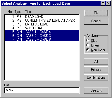
During non-linear analysis, selected load cases may be analysed with linear analysis. This is necessary, for example, when designing some steel members to AS 4100 and others to AS/NZS 4600 - non-linear analysis is used with the former and linear with the latter. When the Analyse > Non-Linear command is selected a dialog box appears showing all existing load cases. This dialog box is shown below. An analysis option indicator is shown for each load case - this may be S (Skip), L (Linear), or N (Non-linear). Select the required analysis option and then click on the load cases to be marked with this analysis option.

Saving Time with Non-Linear Analysis
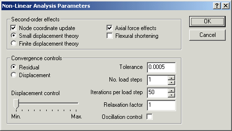
When analysing large structures you may be able to save a significant amount of computer time by clearing the Node coordinate update check mark, as shown in the Non-Linear Analysis Parameters dialog box below.

With these settings, full account is taken of the effects of axial force on member flexural stiffness while the effects of node displacement are approximated by a sidesway correction in the stability function formulation. These settings normally provide the quickest solution where second-order effects must be taken into account. You should check that the results agree with those obtained with both Node coordinate update and Axial force effects selected.
When designing steel members to AS 4100 or NZS 3404 you may find that you can use linear analysis instead of non-linear analysis for all but the final design. These steel design modules automatically use moment amplification when results have been obtained with linear analysis. Where the computed moment amplification factor exceeds 1.4 for any member, however, the design cannot be performed.
