| Applies To | |||
| Product(s): | Microstran | ||
| Version(s): | V8i | ||
| Environment: | N/A | ||
| Area: | Modeling; Analysis | ||
| Original Author: | Richard Collins | ||
What's the Difference Between a Constraint and a Restraint?
In general, both constraints and restraints are limitations imposed on the displacements of nodes. A restraint is simply the elimination of a degree of freedom at a node, that is, the enforcement of a condition of zero displacement for a specified direction at a node. Thus, restraints are supports - points where the displacement is zero.
We might say that the nodes of a plane frame are constrained to displace only in the plane of the structure, but the term constraint is usually reserved for a more complicated kind of condition imposed on the displacements of one or more nodes. For example, there are cases where the rotation in a particular direction of one node must be the same as that of another node. Constraints are used in Microstran as "master-slave constraints" (see below).
Master-Slave Constraints
A master-slave constraint is a condition imposed such that the displacement of a node (called the slave) depends on the displacement of another node (called the master). Master-slave constraints may relate the displacements of a slave node in different directions to different master nodes. If a node has one or more slave nodes, it may not be a slave to another node.
Every displacement component at one node which is determined by displacements at another node results in the elimination of one degree of freedom at the slave node. Since the slave displacement component is uniquely determined by the displacement of the master node, the slave component is no longer an independent degree of freedom of the structure. This is a good reason why master-slave constraints are used - for every degree of freedom saved, there is one row less in the structure stiffness matrix.
If you do not wish to use master-slave constraints you can add members to the structure which effectively impose the same kinematic constraints. You can visualize the effect of master-slave constraints by thinking about the "equivalent" members. For example, the diaphragm action of a concrete floor slab is often simulated by master-slave constraints but it can be approximated by the addition of "truss" members in the plane of the floor which inhibit any plan distortion. Addition of stiff elements to enforce displacement patterns, however, may reduce the accuracy of the analysis. This provides another good reason for using master-slave constraints - the quality of the analysis (measured by the smallness of the maximum condition number) is improved.
With many kinds of large structure, the use of master-slave constraints is desirable for the two reasons given above; reduction in size of the stiffness matrix and improvement in accuracy.
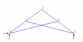
A scissor truss provides an example of how master-slave constraints are used (this is a plane frame structure because there is bending moment in the members). Each chord member is continuous at the point where the web member meets it and there is a pin connecting one web member to the other at the point where they cross. A new node is introduced in each web member at this point. One of these is a slave for the X and Y translational degrees of freedom, and the other node is the master.
The diagram shows the model before the master-slave constraints are input. To complete the model, take these steps:
- Use the Structure>Intersect command to create a new node where the web members cross.
- In Forms Input add a new node with coordinates which are slightly removed from the intersection node (in the plane of structure). You could for example, make one node 1 mm above the intersection point and the other node 1 mm below it. This is necessary because coincident nodes are automatically removed.
- Also in Forms Input, adjust the member connectivity so that the original intersection node is connected only to one web member and the other node is connected only to the other web member.
- Exit from Forms Input and zoom into the point where the web members cross, so that you can see that the two nodes are separate.
- Select the Structure>Attributes>Master-Slave command, make one node the slave and the other the master for the X and Y translational degrees of freedom.
- Finally, introduce pins at each end of the web members and in one of the chord members at the apex.
Click here to download archive file for this example (Scissor.arc - 2K).
Instability and Ill-Conditioning
Instability occurs if a structure or a part of it can move without any resistance. In this case no solution can be obtained. Ill-conditioning occurs if a solution is obtained but with severe loss of numerical precision. An ill-conditioned structure is usually one which is almost unstable, producing gross displacements during analysis. Ill-conditioning may also occur if there is an excessive difference in stiffness from one part of the structural model to another.
Instability and ill-conditioning are properties of the structure, not of the loading condition. They are usually caused by insufficient node restraints, too many member releases or inappropriate values for some section properties. The most common error conditions are described in this section. See also "Common Modelling Problems".
Insufficient Support
If insufficient supports have been specified for overall stability of the structure, analysis is not possible. This condition will be detected before analysis is started and an error of the following form will be reported:
STRUCTURE HAS INSUFFICIENT SUPPORT
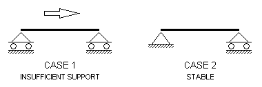
Case 1 in the diagram below shows a simply supported beam with insufficient support.
INSUFFICIENT SUPPORT
Zero Stiffness at Node
If there is zero stiffness for any degree of freedom (DOF) at any node a force or moment could be applied at that DOF without any resistance and so it would be impossible to calculate a displacement in that direction. These errors are detected at an early stage of analysis and reported with an error of the form:
ZERO STIFFNESS AT NODE nnnnn DOF f
where
nnnnn = The node number at which instability was detected.
f = The DOF number in which there was found to be no resistance to displacement.
1 - X direction
2 - Y direction
3 - Z direction
4 - about X axis
5 - about Y axis
6 - about Z axis
A node where a zero stiffness error occurs may be referred to as an unstable node. Unstable nodes can be eliminated by applying a restraint to the zero stiffness DOF at the node. An unstable node is shown in Case 1 in the diagram below. Nodes are represented as solid blocks.

ZERO STIFFNESS AT NODE
Mechanism Instability
If a structure has any part which can move freely it is actually a mechanism and cannot be analysed. A mechanism will be detected during analysis as an attempt to perform impossible numerical operations at a particular DOF and one of the following errors will be reported:
STRUCTURE UNSTABLE AT NODE nnnnn DOF f
or
ZERO PIVOT AT NODE nnnnn DOF f
where "nnnnn" and "f" are as defined above.
Mechanisms may be eliminated by applying a restraint to the DOF reported in the error message but you should consider whether the error is a symptom of a more fundamental problem with the structural model such as a missing support, an inappropriate section property value or an incorrect member release.
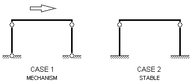
A mechanism is shown in Case 1, in the diagram below, where the frame has pinned supports and also has pins at the top of each column. If any one of the four pins were removed, the structure would be stable.
MECHANISM INSTABILITY
Zero stiffness at a node in a direction which is not parallel to a global axis is also detected as a mechanism during analysis. This type of instability cannot be eliminated by specifying a restraint (in a global axis direction) but by adding a link member or a spring in a non-global axis direction.
Ill-Conditioning
If severe loss of numerical precision occurs during analysis the structure is ill-conditioned. The condition number, reported on the screen after analysis, is a measure of how much precision was lost. When an analysis has been completed with a large condition number being reported, the results should be regarded as being meaningless and the structure may well be unstable. A displaced shape plot of an ill-conditioned structure would usually show gross displacements. Microstran does not arbitrarily decide at what point the ill-conditioning becomes unacceptable so that the user should always check the condition number (see "Report Contents").
After analysis Microstran performs an equilibrium check in which the external forces are compared to the sum of the member forces at each node. If this check shows a discrepancy the following error message will be reported:
LARGE RESIDUAL - POSSIBLE MODELLING ERROR
In this case, a large condition number will also be reported and the results should be regarded as being meaningless. Note that it is possible for ill-conditioning to occur without a discrepancy in the equilibrium check – a satisfactory equilibrium check is not a guarantee that the analysis was successful.
Common Modelling Problems
Unconnected Members
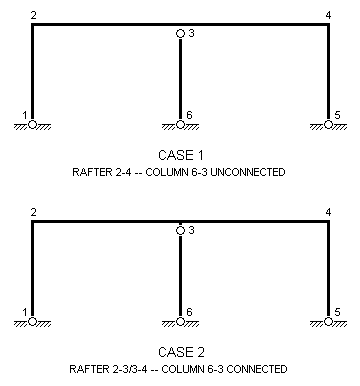
Sometimes, it may not be evident that a single member has been input instead of two or more connected end-to-end. If this occurs, it can give rise to unconnected members at the interior nodes. In the diagram below, for example, if the rafter is input as a single member (2-4) from node 2 to node 4, the central column will not be connected to the rafter and it will be unstable. The rafter must be input as two members, 2-3 and 3-4, so that the central column (6-3) is connected to it.
UNCONNECTED MEMBER
Plane Trusses
If zero stiffness errors are reported at nodes in a plane truss it may be because the structure type is set to "plane frame" while all members are pin-ended. This situation may be avoided by any of the following procedures:
- Set the structure type to "plane truss", in which case Microstran will automatically treat all members as pin-ended and delete rotational DOF.
- Apply node restraints at all DOF where zero stiffness is reported.
- Remove pins in the chord members (since these are often continuous) leaving the web members pin-ended.
- Remove all pins. If the structure is fully triangulated, bending moments will usually be insignificant but if they are not, releases may be inserted as required. This is sometimes the best approach for a preliminary analysis.
A situation where a zero stiffness error will occur in a plane frame is illustrated in Case 1 in the diagram below. In Case 2, where at least one member is rigidly connected to the node, there is no instability. The node is represented in this diagram as a solid block.
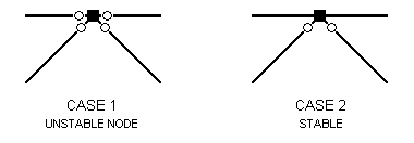
CONTINUOUS CHORD IN PLANE TRUSS
Pin-ended members may also be modelled by specifying a zero for the appropriate section moment of inertia so that the member has no flexural stiffness. In this case, moment releases are unnecessary and should not be used. This modelling technique cannot be used if transverse loads are applied to members, if there are acceleration loads or if you are using non-linear or elastic critical load analysis.
Space Trusses
In a space truss (where all members are pinned at both ends), the structure must be fully triangulated to be stable. Any node in a space truss where all connected members lie in a plane is known as a coplanar node and will be unstable unless there is a restraint or a spring support or a master-slave constraint which inhibits displacement normal to the plane. In the Microstran checking phase, warning messages are issued for all coplanar nodes detected.
Consider, for example, a tower structure modelled as a space truss (see "Example 3 – Space Truss"). Each face panel of the tower will be a plane truss and although it may be stable in its own plane, out-of-plane displacement of the interior nodes of the truss must be inhibited to make the model stable. If the analysis proceeds with any instability of this type existing, a zero stiffness error will occur if the plane is parallel to a global plane. If it is not, instability or ill-conditioning will be reported during analysis.
Large Differences in Stiffness
When very stiff structural elements are being modelled, unreasonably large values should not be input for section properties. For example, when modelling a wide column, a very stiff link member may be used to connect a node on the centre-line with a node on the face of the column. While a value for the moment of inertia of the link of 10E3 times the moment of inertia of the column may yield satisfactory results, a value of 10E20 times that moment of inertia would cause ill-conditioning. This kind of modelling problem can be eliminated altogether by the use of rigid member offsets (see preceding section and "Rigid Member Offsets").
See Also
RAM Instability In Finite Element Analysis
