| Applies To | |||
| Product(s): | Microstran | ||
| Version(s): | V8i | ||
| Environment: | N/A | ||
| Area: | Design | ||
| Original Author: | Richard Collins | ||
General
Microstran may be used to assist in the design and evaluation of fall arrest systems consisting of a static line to which a person is attached by a lanyard incorporating a shock-absorber (personal energy absorber). The static line may be part of a network of cables analysed with Microstran’s catenary cable element option.
Standards such as AS/NZS 1891 and OSHA 1915.159 (U.S. Department of Labor) prescribe maximum arresting forces that may be applied during a fall. The main requirements of these two standards (for persons wearing a full body harness) are summarized in the table below.
| AS/NZS 1891 | OSHA 1915.159 | |
| Length of lanyard | 2 m | 6 ft (1.8 m) |
| Max. free fall distance | 2 m | 6 ft (1.8 m) |
| Falling mass | 100 kg | 310 lb (140 kg) |
| Max. arresting force | 6 kN | 1800 lb (8 kN) |
| Max. deceleration distance | 3.5 ft (1.07 m) | |
| Min. "pull-out" force | 2 kN | |
| Typical "pull-out" force | 850 lb (3.75 kN) | |
| Min. static tensile strength | 15 kN | 5000 lb (22.2 kN) |
The shock-absorbing device that must be attached to the lanyard typically contains multiple layers of the lanyard webbing material fastened together with stitching designed to fail progressively ("rip-stitching"). The pull-out force is the force required to initiate irreversible extension of the device. Shock-absorbing devices that comply with the above standards ensure that the maximum deceleration force is not exceeded when the lanyard is attached to a rigid anchorage. Maximum deceleration forces will be reduced by any deflection in the supporting structure, and when this is a cable the deflection may be appreciable.
Cable networks may be analysed in Microstran if the catenary cable option is available. The load applied to the cable during a fall event may be assumed to be the maximum arresting force if the shock-absorbing device complies with the applicable standard. An accurate determination of the maximum dynamic force applied to the cable during a fall event requires consideration of the equilibrium of the falling mass together with the load-deflection characteristics of the combined structure/lanyard. This may be done in an Excel spreadsheet, in which the period of time from the end of the free-fall to the instant of maximum extension of the lanyard is considered in a large number of very small time increments.
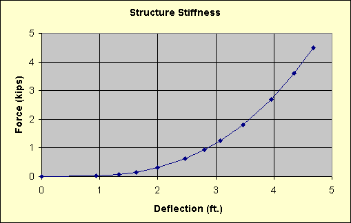
Structure Stiffness
The stiffness of the cable network at the point of attachment of the lanyard may be represented in a load-deflection curve as shown in the diagram below.

A load case is required for each point on the curve. As the structure is highly non-linear, several points will be required.
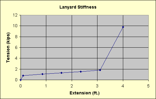
Lanyard Stiffness
The characteristics of the shock-absorbing lanyard may be represented in a load-deflection curve as shown in the diagram below.

The first discontinuity in this curve represents first yield or "pull-out", the second is the point of full extension, and the last point represents the ultimate load. The lanyard should never be loaded past the point of the second discontinuity because the falling mass should have been decelerated to a stop before this point is reached.
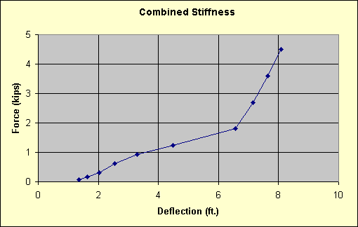
Combined Stiffness
The load-deflection characteristics of the structure and the lanyard are combined in the spreadsheet into a single relationship by adding together the flexibilities of each. The resulting load-deflection diagram is shown below.

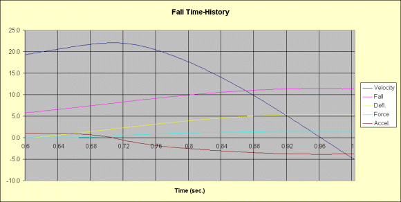
The Spreadsheet
The spreadsheet tabulates 200 time intervals, each of 2 milliseconds. For each instant, using values from the previous instant and the load-deflection properties, formulas in the spreadsheet compute the velocity, the fall distance, the deflection of the combined structure/lanyard, the decelerating force, and the acceleration of the falling mass. Results are plotted in a graph, shown below. The spreadsheet summarizes maximum deflection, maximum force in the lanyard, and the maximum deceleration of the mass.

The spreadsheet is available at Free Stuff.
