| Applies To | |||
| Product(s): | Microstran | ||
| Version(s): | V8i | ||
| Environment: | N/A | ||
| Area: | Analysis; Modeling | ||
| Original Author: | Richard Collins | ||
Analysis of Tilt-Up Panels with Microstran
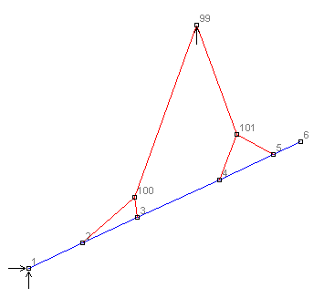
An Excel spreadsheet is available to assist in the use of Microstran for the analysis of tilt-up panels. The spreadsheet relates to the structure shown below:

The red members are slings, modelled with catenary cable elements, and the blue members represent the reinforced concrete panel. There is a pin support at node 1 and a vertical support at node 99. There are sheaves at nodes 99, 100, and 101, so that the tension in each sling is the same on each side of the supporting sheave.
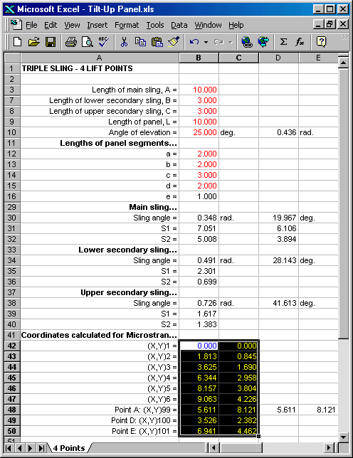
The spreadsheet is shown below. Values shown in red are entered and the coordinates of all nodes are calculated automatically. The X and Y coordinates of the nodes are selected in Excel and copied to the Windows clipboard by clicking the Copy button. These coordinates are then pasted into the Microstran node coordinate view and the correct geometry for the tilt-up panel and slings is instantly displayed.

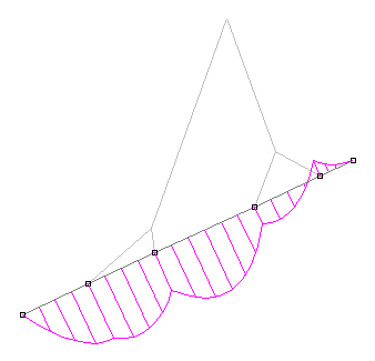
Non-linear analysis is performed in Microstran and the results can be displayed in various ways. The bending moment diagram for the tilt-up panel at an elevation of 25 degrees is shown below:

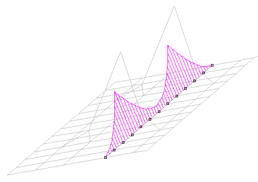
As shown below, the model may be extruded in the Z global axis direction to create a 3-D model for consideration of bending moment in the transverse direction.

The spreadsheet is available at Free Stuff.
